I should have accepted Walt's challenge straight up instead of adding my twist in pursuit of my theory, which was based on assumptions that turned out to be false. Another lesson learned the hard way. So here I applied 2" wide shipping tape just as Walt's challenge suggested. This time I scribbled about half-way around the circumference to simulate the meaty part of the palm doing that as demonstrated earlier. Also I applied graphite from the pencil to the edges of the square dowel. I can believe that the machining process for making the actual bayonet lug could leave some roughness on those edges and that dirt and debris could cling to those edges more so than the smoother flat surfaces. It is not difficult to apply the tape such that it follows the contours of the bayonet lug. Here are a couple of photos:
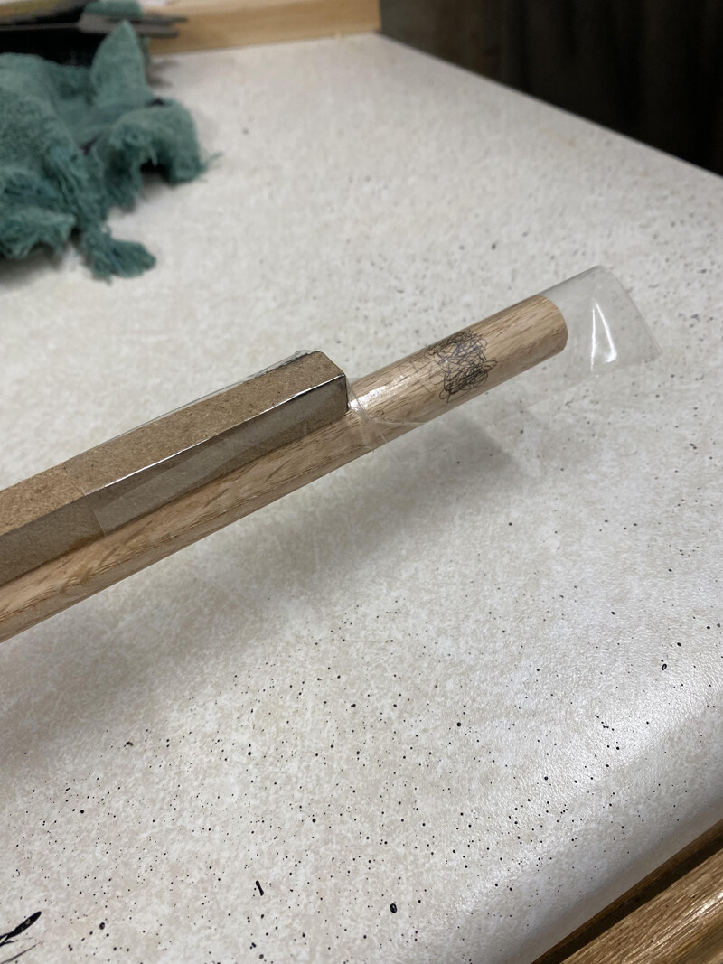
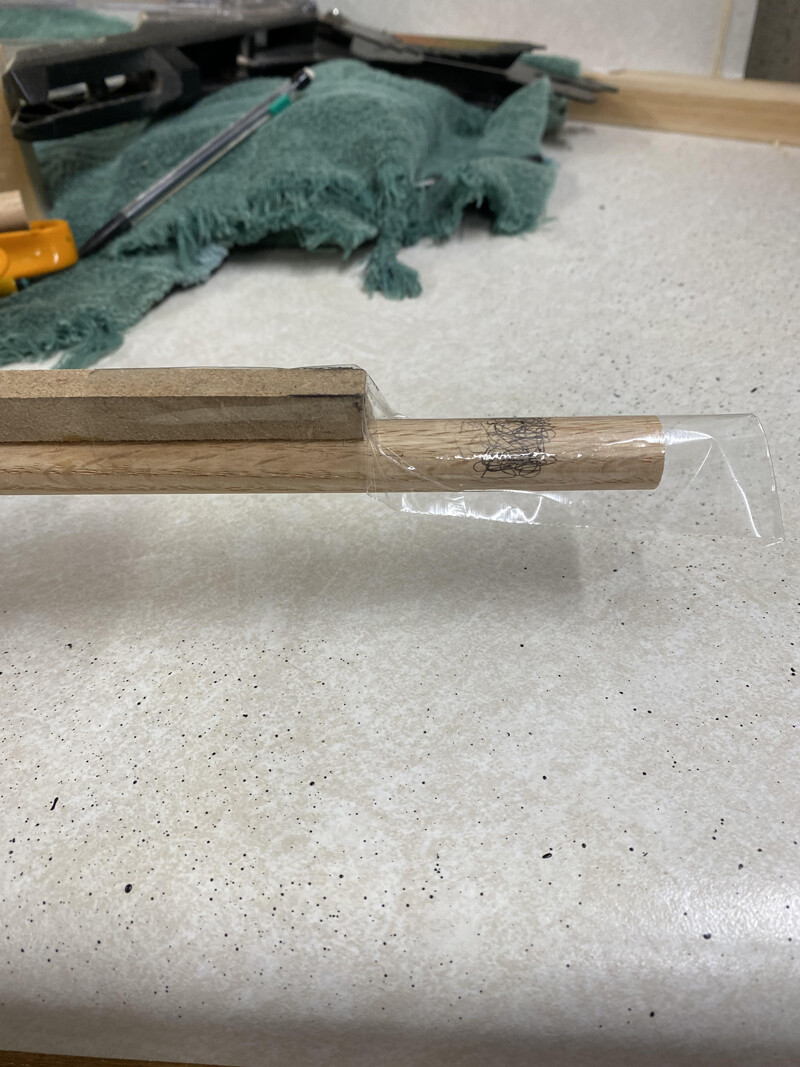
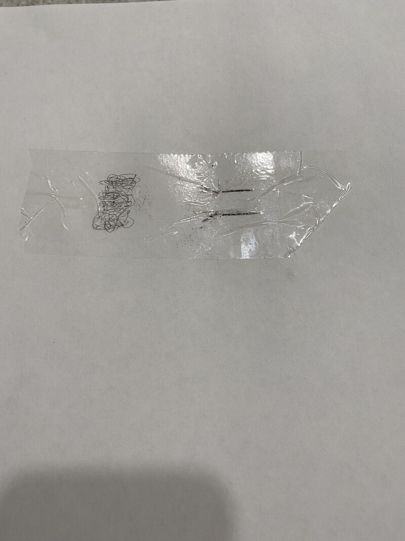
And here is a photo of the tape applied to a sheet of printer paper:
A few comments about this experiment:
It is a crude experiment only done as a proof of concept.
The square wooden dowel was made when Walt stated it needed to be 3/8". I assumed both the width and the height were the same. I made it out of a scrap piece of MDF which was a little thicker than 3/8" (7/16") thinking for the experiment I would rather have it a little oversized than undersized. We later learned that the slot for the bayonet lug is only 5/16" wide. And I would think that the actual lug is slightly under that size. Therefore the square wooden dowel is significantly wider than the actual bayonet lug. And so the lines on the tape are a little further apart than what we see on images of the actual lift.
As can be seen in the photos, I manipulated the tape to stick to the vertical surface of the lug. After looking at the resulting lift, I believe that Day probably didn't do that and left that part of the tape a little loose and unstuck.
The shipping tape that I used is probably a bit different than the tape used back in 1963. But it is relatively thin for today's shipping tape (some of the tape available today is thicker and less pliable).
When I zoom an image of the actual 1963 lift such that the lines are about 5/16" apart, the width of the tape is about 2". And the rough experiment I did this morning indicates to me that the palm print (scribbling), the distance (if corrected as stated above) between the lines, and the width of the tape are reasonably proportional to each other when compared to the same proportions in the image of the actual lift.
Based on the distance between the lines and the palm print as seen in the images of the lift, it appears to me that the bayonet must have been partially in the palm, when the latent print was left on the bottom of the barrel, as depicted in the first of the photos I posted earlier suggesting how the barrel was held.
Based on this experiment, I believe that Day lifted some dirt/debris from the edges of the bayonet lug that form the previously mysterious lines.


